

First project. Flashing LED Arduino by clicking on the smartphone
Learning to program microcontrollers always starts with a very simple example "Hello world" - LED blinked. The study of this online-service also offer to start with a very simple example - we just blinked LED. However, we will blink them remotely by pressing a button on the screen of our smartphone.
All that we shall do with you, you can look at the video at the end of this page.
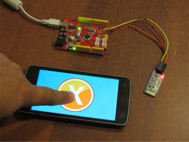
We have a standard Arduino board and module Bluetooth HC-04. You can use almost any Arduino board and any Bluetooth Module HC-04 series (05/06/07). These Bluetooth modules have a default operating mode UART - direct transmission, and require no setting.
Design the control interface
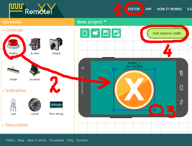
We go to the editor interfaces site and draw our interface. The interface consists of a single button. Click the left-mouse on management item "Button" and set it in the working field. Since only one button, it can be stretched to fill the screen. To do this, select the buttons, and blue squares for border allocation change its size, the mouse moves it to the desired position. The picture shows what should happen:
Generate source code
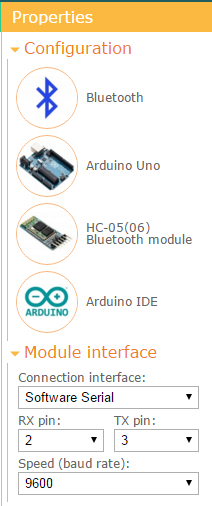
Our interface design is ready. Before you get the source code for our microcontroller, you must specify for which platform we want to get it. Our platform - Arduino. To communicate with the Bluetooth module will use SoftwareSerial. This will give us an opportunity to connect the Bluetooth module to virtually any microcontroller pins. This setting must be selected in project configuration field.
Now press the button "Get source code". If you are not registered, you must register to get a project source code.
On the download page of the source code is the code of the sketch program for the Arduino microcontroller. This code implements a graphical management interface that was created in the editor. To compile this sketch also need to install the RemoteXY library. Download library by link and install in the Arduino IDE using instruction.
/////////////////////////////////////////////
//        RemoteXY include library         //
/////////////////////////////////////////////

/* RemoteXY select connection mode and include library */
#define REMOTEXY_MODE__SOFTWARESERIAL
#include <SoftwareSerial.h>
#include <RemoteXY.h>

/* RemoteXY connection settings */
#define REMOTEXY_SERIAL_RX 2
#define REMOTEXY_SERIAL_TX 3
#define REMOTEXY_SERIAL_SPEED 9600

/* RemoteXY configurate  */
unsigned char RemoteXY_CONF[] =
  { 255,1,0,0,0,13,0,16,31,0,1,0,28,10,44,44,2,31,88,0 };

/* this structure defines all the variables of your control interface */
struct {

    /* input variable */
  unsigned char button_1; /* =1 if button pressed, else =0 */

    /* other variable */
  unsigned char connect_flag;  /* =1 if wire connected, else =0 */

} RemoteXY;

/////////////////////////////////////////////
//           END RemoteXY include          //
/////////////////////////////////////////////

#define PIN_BUTTON_1 13

void setup()
{
  RemoteXY_Init ();

  pinMode (PIN_BUTTON_1, OUTPUT);

  // TODO you setup code

}

void loop()
{
  RemoteXY_Handler ();

  digitalWrite(PIN_BUTTON_1, (RemoteXY.button_1==0)?LOW:HIGH);

  // TODO you loop code
  // use the RemoteXY structure for data transfer

}
Click the "Download" link and download the source code of a zip archive. Unzip it and open the file project.ino in the IDE Arduino.
Note that in the project (function main) already as an example our button connected to the pin 13. This pin is standard for Arduino board is a LED that allows testing program. Them we are going to blink. We do not need to fix anything in this part of the code.
We generally do not need to be corrected. The code compiles without errors completely. But do not be in a hurry, we still need to set up a connection with the Bluetooth module.
Connecting the Bluetooth module
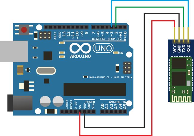
Now we need to physically connect a Bluetooth module to the board Arduino. Module HC-04 has the 4th contact (they are signed directly on the board). Two of them - the power. For module used a standard Power + 5V from Arduino board.
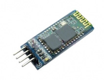
The other two - a UART interface: RX and TX, responsible for receiving and transmitting data. RX is necessary to connect to pin on the Arduino, which we have function TX, TX and pin to pin on the Arduino, having a function RX. How do you know which pins on the Arduino are responsible for the RX and TX module communication? Very simple.
In the sketch code there are two definitions pins, it connected to the Bluetooth module. It has two definitions, find these lines of code. They defined, what pins will be used when configuring SerialSoftware:
/* RemoteXY connection settings */
#define REMOTEXY_SERIAL_RX 2
#define REMOTEXY_SERIAL_TX 3
Thus, contact RX of Bluetooth module connected to pin number 3 of board Arduino, and contact TX - to pin number 2 of the board. Of course you can change the pin numbers of your choice (see the documentation at SerialSoftware, since not all the pins can be used in emulation software UART).
Now you can download code to microcontroller. Do it!
Download the mobile app and connect to our Arduino
Go to the section of the site "Download mobile application" and download to your smartphone or tablet the application. Of course your smartphone/tablet should have a built Bluetooth.
Run the application. Turn on Bluetooth, if it is off. Automatically begins searching for devices. All devices found will be listed.
Default modules HC-04 (05/06/07) are programmed name "INVOR" or "HC-04" ("HC-05", "HC-06"). If the list of devices there is this name - it is your devise. We click on it. After some time required for connection to the module, you will be prompted to enter the password for pairing. The modules of HC-04 (05/06/07) have programmed password is "1234". Enter it. And end, we have opened our interface with a big button on the full screen!
Click on this button and look, as LED is blink on the board Arduino! Quite simply, it works!
 Русский