

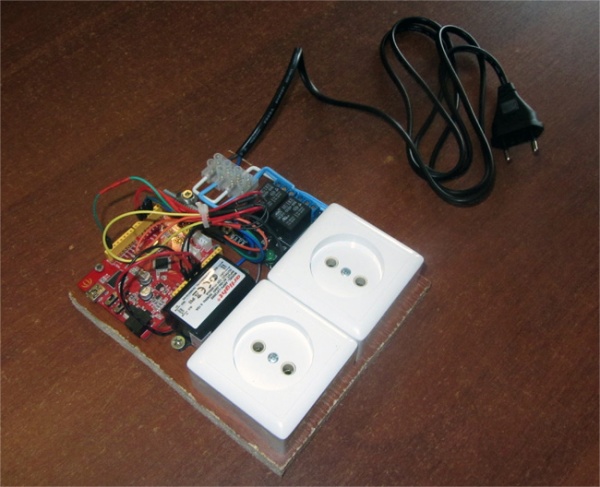
Smart power socket control from your smartphone via Bluetooth
Smart power socket via Arduino, what could be easier. Article about the project controlled smart power socket from your smartphone via Bluetooth. Control is implemented using the service RemoteXY. Two power sockets, separately controlled from a smartphone, placed on a single platform with all the necessary electronics. The area of use of smart power socket is large enough. You will be able to remotely turn on and off electrical devices. Also, this project can be used as an example to create more complex devices for controlled electrical devices.
To implement the project, we used the following components:
- Arduino UNO or compatible board.
- Relay module 2 channels with 5V.
- AC-DC power supply miniature 12V, 0.15A.
- Bluetooth module HC-05.
- Power sockets 2 pcs. (external installation)
- Power plug with a wire.
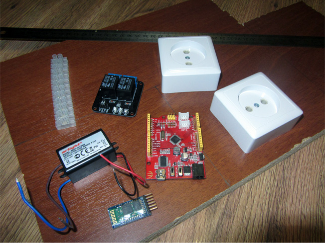
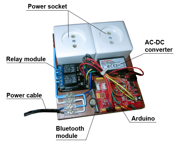
All the components we have placed on the platform of the plate wooden board size 155x135 mm. Fixing all the components to the platform performed with screws and pre-drilled holes in the platform. Accommodation option parts you can see in the picture. Arduino board placed in such a way that would have easy access to a USB port for programming.
The figure shows the connection diagram components. Bluetooth module is connected to pins 2 and 3 Arduino. For controlling of relay module used pins 4 and 5. The entire setup is powered from input high voltage through the power supply - a miniature AC-DC converter output 12V supply voltage. This voltage is supplied to the Arduino on pin Vin.
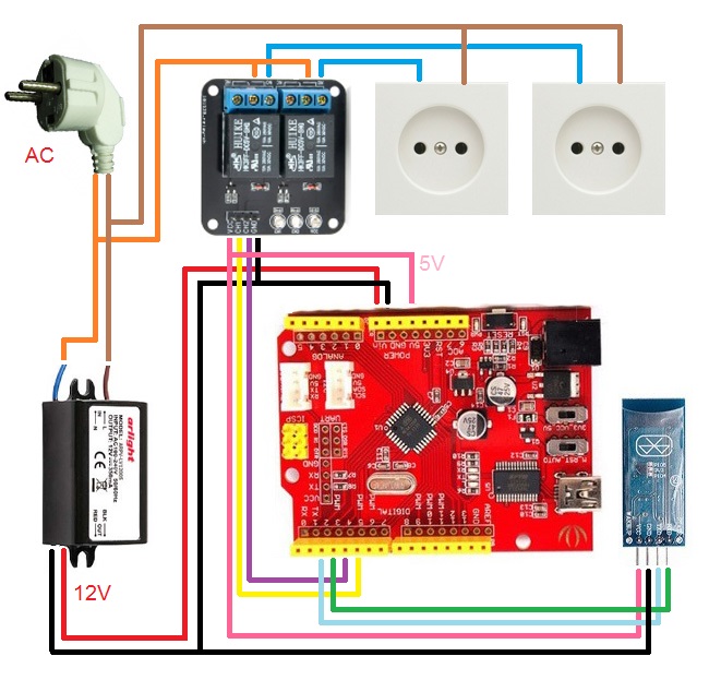
All high-voltage wiring is aluminum wire conductor diameter 1.2 mm. Be very cautious and careful when installing high-voltage wires!
Software
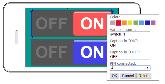
Use online editor RemoteXY create graphical user interface. At the interface set two large switch. In the properties of the switch for one of them, select the property "pin connected" pin 4 for another pin 5. This will automatically receive a source code to manage pins with these switches. In the project settings, select the type of connection via Bluetooth module via SoftwareSerial.
Generate a project source code and upload it to the Arduino. The source code is shown below.
/////////////////////////////////////////////
//        RemoteXY include library         //
//   use ANDROID app version 3.1.1 or up   //
/////////////////////////////////////////////

/* RemoteXY select connection mode and include library */
#define REMOTEXY_MODE__SOFTWARESERIAL
#include <SoftwareSerial.h>
#include <RemoteXY.h>

/* RemoteXY connection settings */
#define REMOTEXY_SERIAL_RX 2
#define REMOTEXY_SERIAL_TX 3
#define REMOTEXY_SERIAL_SPEED 9600

/* RemoteXY configurate  */
unsigned char RemoteXY_CONF[] =
  { 2,0,30,0,2,5,2,0,6,2
  ,88,29,1,79,78,0,79,70,70,0
  ,2,0,6,33,88,29,6,79,78,0
  ,79,70,70,0 };

/* this structure defines all the variables of your control interface */
struct {

    /* input variable */
  unsigned char switch_1; /* =1 if switch ON and =0 if OFF */
  unsigned char switch_2; /* =1 if switch ON and =0 if OFF */

    /* other variable */
  unsigned char connect_flag;  /* =1 if wire connected, else =0 */

} RemoteXY;

/////////////////////////////////////////////
//           END RemoteXY include          //
/////////////////////////////////////////////

#define PIN_SWITCH_1 4
#define PIN_SWITCH_2 5


void setup()
{
  RemoteXY_Init ();

  pinMode (PIN_SWITCH_1, OUTPUT);
  pinMode (PIN_SWITCH_2, OUTPUT);

  // TODO you setup code

}

void loop()
{
  RemoteXY_Handler ();

  digitalWrite(PIN_SWITCH_1, (RemoteXY.switch_1==0)?LOW:HIGH);
  digitalWrite(PIN_SWITCH_2, (RemoteXY.switch_2==0)?LOW:HIGH);

  // TODO you loop code
  // use the RemoteXY structure for data transfer

}
Now you can use RemoteXY application for Android for connect to your device and control power sockets.
 Русский