

Smartphone controlled сardboard robot
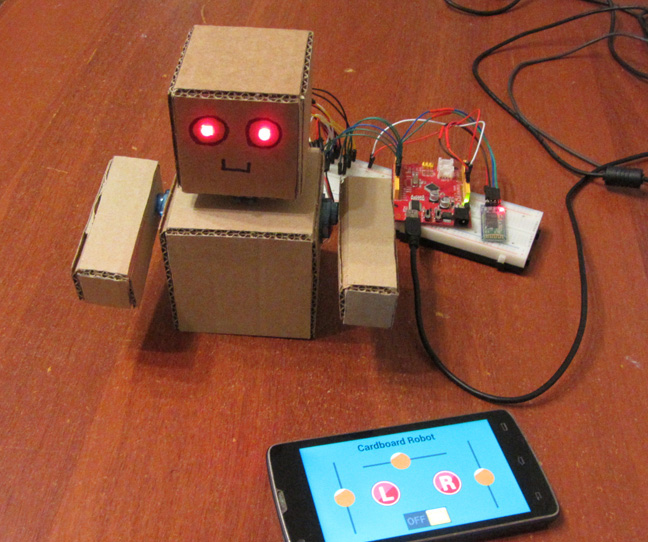
In this article, we'll build a cardboard robot on three servo controlled by Arduino. The robot will move his hands and turn his head. To develop the control will use the service RemoteXY, which enables you to control robot with a smartphone via Bluetooth.
Robot body
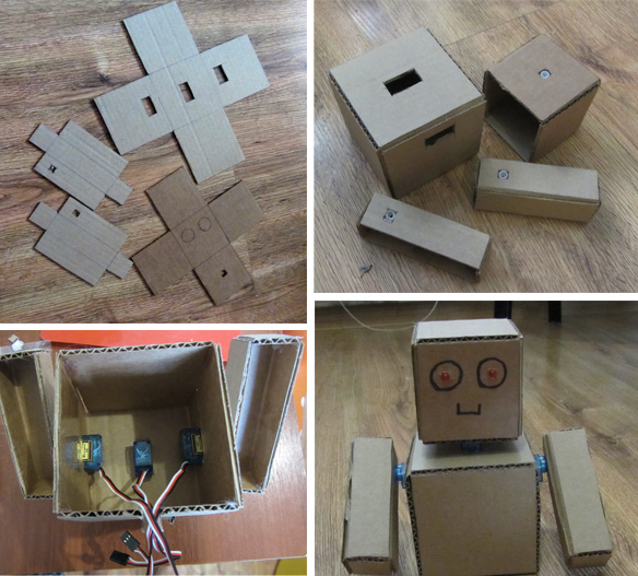
The robot consists of four parts, cut out of cardboard. This torso, head and two hands. All parts are cut with a knife. Details can be glued together using plastic glue gun to heat up. To install the servos on the body is necessary to cut rectangular holes. To install the servo in the holes using the same plastic glue. On the head and the hands of robot, where the shaft of servo connect to the servo arm that are glued to the body from the inside by means of the same plastic glue. We will not give the exact dimensions and drawings, you should not be difficult to repeat the design.
At the head of the robot cut the two holes into which fit the two LEDs. This will be the eye. Eyes will also be light remotely.
Electric scheme
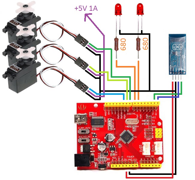
For stable operation of the robot, servo drives must be powered from a another power supply 5V. Arduino voltage regulator can not provide the required amperage for all three servos. Series with the LEDs need to enable resistor 680 ohms.
Control interface
Open the editor interfaces RemoteXY.com site and create a management interface, shown in the image below. Interfaces are included the right and left slider to the right-hand and left-hand and to rotate the head slider. Set two buttons to control the eyes. And set the switch. We will use it to start automatic blinking eyes.
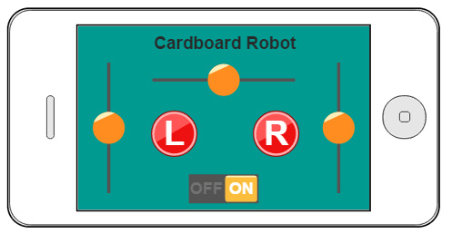
Rename the sliders, call them slider_left, slider_right and slider_head, respectively. And rename the buttons. Call them button_left and button_right, respectively.
Since our project involves the use of the library servo.h, select the project settings, the generate source code for for Arduino (Serial), library version. The library servo.h conflicts with the library SoftwareSerial.h, on this will not use it.
Generate and download the source code of the project a graphical interface to your computer. Don't forget to download and install the library RemoteXY for the Arduino IDE. Compile and upload the sketch in the Arduino board. Using the mobile app RemoteXY verify that your smartphone can connect with your new project. Do not forget that the Bluetooth module must be connected to the serial port hardware to pins 0 (RX) and 1 (TX). If your smartphone is connected successfully, then go ahead.
The generated structure of variables RemoteXY in the sketch of Arduino project should be such:
/* this structure defines all the variables of your control interface */
struct {

    /* input variable */
  unsigned char slider_left; /* =0..100 slider position */
  unsigned char slider_right; /* =0..100 slider position */
  unsigned char slider_head; /* =0..100 slider position */
  unsigned char button_left; /* =1 if button pressed, else =0 */
  unsigned char button_right; /* =1 if button pressed, else =0 */
  unsigned char switch_1; /* =1 if switch ON and =0 if OFF */

    /* other variable */
  unsigned char connect_flag;  /* =1 if wire connected, else =0 */

} RemoteXY;
Control programm
The control program must perform the following tasks:
- Convert control effects sliders in the commands Servo.
- Convert pressing button of eyes in the two LEDs, if the switch switch_1 is off.
- Blinking LEDs, if the switch switch_1 is turned on. In this case, pressing buttons has no effect on the LEDs.
It is also very important to note that the program should be running out continuously. It is for this function loop, the main loop of the program, you can not use the pause. For example, a pause mode, often used in two LED-blinking, waiting time between switching the LED. In this case, such an approach would lead to errors. In each cycle, loop is called the function RemoteXY_Handler (), which is responsible for the exchange of data with the smartphone via the Bluetooth module. If this function is not called for a long time, it will not be able to properly carry out the exchange of data. How to solve the problem of timing between switching LEDs? Very simply, using built-in timer. The following is the source code control.
/////////////////////////////////////////////
//        RemoteXY include library         //
/////////////////////////////////////////////

/* RemoteXY select connection mode and include library */
#define REMOTEXY_MODE__SERIAL
#include <RemoteXY.h>

/* RemoteXY connection settings */
#define REMOTEXY_SERIAL Serial
#define REMOTEXY_SERIAL_SPEED 9600

/* RemoteXY configurate  */
unsigned char RemoteXY_CONF[] =
  { 6,0,79,0,1,5,4,0,5,7
  ,11,56,2,4,0,84,7,11,56,2
  ,4,128,20,13,60,11,2,129,0,26
  ,3,49,6,0,208,161,97,114,100,98
  ,111,97,114,100,32,82,111,98,111,116
  ,0,1,0,25,29,16,16,1,76,0
  ,1,0,60,29,16,16,1,82,0,2
  ,0,38,51,24,10,2,79,78,0,79
  ,70,70,0 };

/* this structure defines all the variables of your control interface */
struct {

    /* input variable */
  unsigned char slider_left; /* =0..100 slider position */
  unsigned char slider_right; /* =0..100 slider position */
  unsigned char slider_head; /* =0..100 slider position */
  unsigned char button_left; /* =1 if button pressed, else =0 */
  unsigned char button_right; /* =1 if button pressed, else =0 */
  unsigned char switch_1; /* =1 if switch ON and =0 if OFF */

    /* other variable */
  unsigned char connect_flag;  /* =1 if wire connected, else =0 */

} RemoteXY;

/////////////////////////////////////////////
//           END RemoteXY include          //
/////////////////////////////////////////////

#include <Servo.h>

#define PIN_LED_LEFT 6
#define PIN_LED_RIGHT 7

#define PIN_LEFT_SERVO 8
#define PIN_RIGHT_SERVO 9
#define PIN_HEAD_SERVO 10

Servo left_servo;
Servo right_servo;
Servo head_servo;

unsigned char led_state = 0;
unsigned long led_time=0;
unsigned long prev_time=0;


void setup()
{
  RemoteXY_Init ();

  // TODO you setup code

  pinMode (PIN_LED_LEFT, OUTPUT);
  pinMode (PIN_LED_RIGHT, OUTPUT);

  left_servo.attach(PIN_LEFT_SERVO);
  right_servo.attach(PIN_RIGHT_SERVO);
  head_servo.attach(PIN_HEAD_SERVO);

  RemoteXY.slider_left=50;
  RemoteXY.slider_right=50;
  RemoteXY.slider_head=50;

}

void loop()
{
  RemoteXY_Handler ();

  // TODO you loop code
  // use the RemoteXY structure for data transfer
  unsigned long time = millis();
  unsigned long d_time = time - prev_time;
  prev_time = time;


  if (RemoteXY.switch_1==0) {
    digitalWrite(PIN_LED_LEFT, (RemoteXY.button_left==0)?LOW:HIGH);
    digitalWrite(PIN_LED_RIGHT, (RemoteXY.button_right==0)?LOW:HIGH);
  }
  else {
    led_time+=d_time;
    if (led_time>500) {
      if (led_state==0) led_state=1;
      else  led_state=0;
      led_time-=500;
    }
    digitalWrite(PIN_LED_LEFT, (led_state==0)?LOW:HIGH);
    digitalWrite(PIN_LED_RIGHT, (led_state==1)?LOW:HIGH);
  }

  left_servo.writeMicroseconds(RemoteXY.slider_left*20+500);
  right_servo.writeMicroseconds(2500-RemoteXY.slider_right*20);
  head_servo.writeMicroseconds(RemoteXY.slider_head*20+500);

}
At the beginning of the program determines the number of pins that will be used for the eyes and LEDs to control three servos. Function setup initializes the LED pins as outputs, initializes classes servos. Next, set the initial positions of the sliders in the middle position.
In function loop the first is called RemoteXY_Handler. It then computes the amount of time that has passed since the beginning of the previous cycle function loop, in milliseconds. As this time interval is used to calculate the time to blinked LED. If the switch is switch_1 is off, the state of the buttons button_left and button_right is directly transmitted to the control pins-LED eyes. If switch_1 is enabled, the algorithm is implemented blinking eyes. Light duration of one eye is 500 milliseconds.
Next, position the sliders control arms and head are converted to pulse width to control the servos. Slider changes its state from 0 to 100, while the servo control pulse duration should vary from 500 to 2500 ms. Please note that the servo right hand moves in the opposite direction, and this is reflected in the transformation formula.
Download
Project for Arduino - Cardboard Robot
 Русский