

Manage the Arduino-robot using the G-sensor on your smartphone
In this article you will learn how to use this service RemoteXY very easy to set up a remote control robot platform or two motors car. The robot we will manage with the control element "joystick" that can work with G-sensor of your smartphone. At the end you will find the video and can see what we've got.
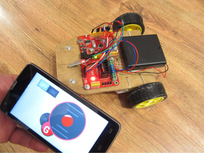
We have assembled a very simple two-wheeled platform that would show you how to build a remote control system. The platform consists of the following components (we do not claim the workmanship, the platform is assembled to demonstrate the capabilities of the resource RemoteXY):
- Сhassis - we excised from its sheet material;
- The front wheel - wheel turns 360 degrees;
- Gear motors 2 pcs.;
- Wheel, with the axis suitable for geared motors 2 pcs. Wheels we bought together with geared motor;
- Battery compartment with a switch on the 4th AA type batteries;
- Arduino, we used all the same clone Seeeduino;
- Bluetooth HC-06 module;
- Motor driver chip L298N;
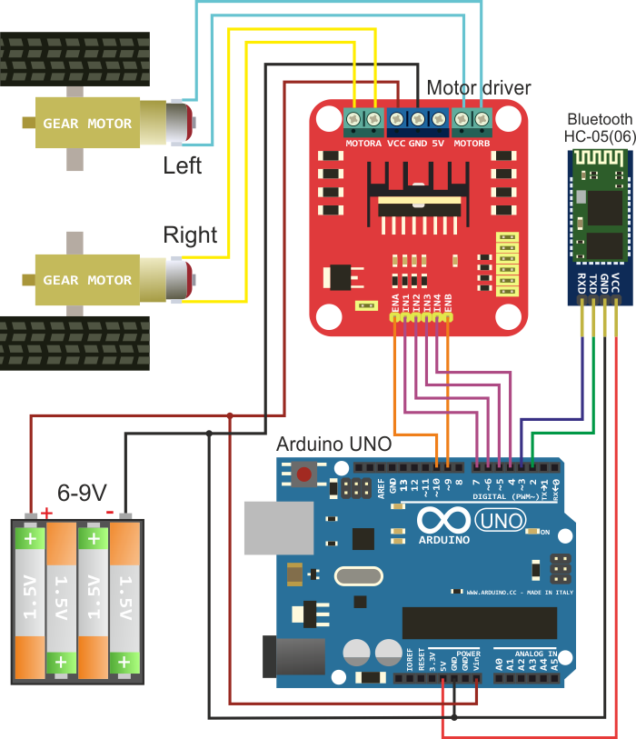
Electrical wiring and all modules machines represented in the following figure.
Management program
Use editor of this resource and construct the following interface control:
Set in the middle of the screen "joystick". In the properties of the joystick to select additional control "Enable G sensor". Select the switch position G-Sensor "bottom-left". The same settings can change the color to red. In the future, we will be a joystick to control the movement of the machine.
Set "Switch." Put it to the left of the joystick. You can also change its color. Switch, we will drive the LED on the Arduino board at pin 13.
If you did everything right, you should have roughly the management interface:
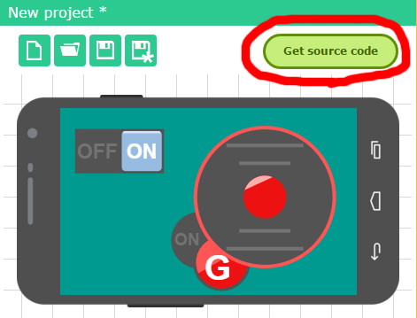
In the project settings, select the target platform, for which we get the source code: "Arduino (SoftwareSerial), library version". Push the button "Get the code" and download the source code on your computer. By link download library RemoteXY and install it in the Arduino IDE.
Open the downloaded sketch in the IDE Arduino. Perfect sketch compiles without errors. However, it certainly is no code to manage our machine. Our task is to corrected this code. For correct, we will use the downloaded example.
Pay attention to the definition of the structure RemoteXY in the sketch of project. The structure contains fields that fully comply with the established controls on the user interface. We see the variables joystick_1_x and joystick_1_y, reflecting the x and y coordinates of joystick, as well as variable switch_1, reflecting the switch.
/* this structure defines all the variables of your control interface */
struct {

    /* input variable */
  signed char joystick_1_x; /* =-100..100 x-coordinate joystick position */
  signed char joystick_1_y; /* =-100..100 y-coordinate joystick position */
  unsigned char switch_1; /* =1 if switch ON and =0 if OFF */

    /* other variable */
  unsigned char connect_flag;  /* =1 if wire connected, else =0 */

} RemoteXY;
The next is the main program code, which is already built controls the motors of our robot platform. You can simply copy this code below to your sketch, or selectively add the necessary pieces of code in the downloaded example.
/////////////////////////////////////////////
//        RemoteXY include library         //
/////////////////////////////////////////////

/* RemoteXY select connection mode and include library */
#define REMOTEXY_MODE__SOFTWARESERIAL
#include <SoftwareSerial.h>
#include <RemoteXY.h>

/* RemoteXY connection settings */
#define REMOTEXY_SERIAL_RX 2
#define REMOTEXY_SERIAL_TX 3
#define REMOTEXY_SERIAL_SPEED 9600

/* RemoteXY configurate  */
unsigned char RemoteXY_CONF[] =
  { 255,3,0,0,0,29,0,16,13,0,5,15,49,9,43,43,1,26,31,2,
  0,6,7,32,15,5,26,31,31,79,78,0,79,70,70,0 };

/* this structure defines all the variables of your control interface */
struct {

    /* input variable */
  signed char joystick_1_x; /* =-100..100 x-coordinate joystick position */
  signed char joystick_1_y; /* =-100..100 y-coordinate joystick position */
  unsigned char switch_1; /* =1 if switch ON and =0 if OFF */

    /* other variable */
  unsigned char connect_flag;  /* =1 if wire connected, else =0 */

} RemoteXY;

/////////////////////////////////////////////
//           END RemoteXY include          //
/////////////////////////////////////////////
/* defined the right motor control pins */
#define PIN_MOTOR_RIGHT_UP 7
#define PIN_MOTOR_RIGHT_DN 6
#define PIN_MOTOR_RIGHT_SPEED 10

/* defined the left motor control pins */
#define PIN_MOTOR_LEFT_UP 5
#define PIN_MOTOR_LEFT_DN 4
#define PIN_MOTOR_LEFT_SPEED 9

/* defined the LED pin */
#define PIN_LED 13


/* defined two arrays with a list of pins for each motor */
unsigned char RightMotor[3] =
  {PIN_MOTOR_RIGHT_UP, PIN_MOTOR_RIGHT_DN, PIN_MOTOR_RIGHT_SPEED};
unsigned char LeftMotor[3] =
  {PIN_MOTOR_LEFT_UP, PIN_MOTOR_LEFT_DN, PIN_MOTOR_LEFT_SPEED};

/*
   speed control of the motor
   motor - pointer to an array of pins
   v - motor speed can be set from -100 to 100
*/
void Wheel (unsigned char * motor, int v)
{
  if (v>100) v=100;
  if (v<-100) v=-100;
  if (v>0) {
    digitalWrite(motor[0], HIGH);
    digitalWrite(motor[1], LOW);
    analogWrite(motor[2], v*2.55);
  }
  else if (v<0) {
    digitalWrite(motor[0], LOW);
    digitalWrite(motor[1], HIGH);
    analogWrite(motor[2], (-v)*2.55);
  }
  else {
    digitalWrite(motor[0], LOW);
    digitalWrite(motor[1], LOW);
    analogWrite(motor[2], 0);
  }
}

void setup()
{
  /* initialization pins */
  pinMode (PIN_MOTOR_RIGHT_UP, OUTPUT);
  pinMode (PIN_MOTOR_RIGHT_DN, OUTPUT);
  pinMode (PIN_MOTOR_LEFT_UP, OUTPUT);
  pinMode (PIN_MOTOR_LEFT_DN, OUTPUT);
  pinMode (PIN_LED, OUTPUT);

  /* initialization module RemoteXY */
  RemoteXY_Init ();

}

void loop()
{
  /* event handler module RemoteXY */
  RemoteXY_Handler ();

  /* manage LED pin */
  digitalWrite (PIN_LED, (RemoteXY.switch_1==0)?LOW:HIGH);

  /* manage the right motor */
  Wheel (RightMotor, RemoteXY.joystick_1_y - RemoteXY.joystick_1_x);
  /* manage the left motor */
  Wheel (LeftMotor, RemoteXY.joystick_1_y + RemoteXY.joystick_1_x);
}
At the beginning of defined a pins that will be used to control the motors. Further - pins are grouped into two arrays, both left and right motor respectively. To control each motor via the driver chip L298N necessary to use three signals: two discrete, the rotating direction of the motor, and one analog, determining the rotational speed. Calculation this pins we have engaged in the function Wheel. The input to the function is passed a pointer of pin's array selected motor and the speed of rotation as a signed value from -100 to 100. If you value of speed is 0, the motor is switched off.
In a predetermined function setup configured are outputs pins. For analog signal used pins, which can operate as a PWM converters. This pins 9 and 10, they do not require configured in the IDE Arduino.
In a predetermined function loop in each iteration of program calling the handler RemoteXY library. Further there is the control of LED, then controls the motors. For motor control read the joystick coordinates X and Y from fields structure of RemoteXY. Based on the coordinates is operation to calculate the speed of each motor, and call function Wheel, is set the speed of the motor. These calculations are performed in each cycle of the program, ensuring continuous control calculations pins of motors based on the coordinates of the joystick.
Download the resulting sketch in Arduino controller. Download and run the mobile app to your smartphone or tablet. Connect with your robot device and you can control it. Joystick can be operated in the normal mode by moving the slider with your finger. You can select G-sensor, and the robot will move depending on the slope of your smartphone.
If your device after building, one or both motors rotate in the opposite direction, reversing the connection when connecting the motor.
 Русский